


Contents: Basic concepts ↧ ABS system components ↧ Technical specifications ↧ Tightening torques for threaded… ↧ ABS Block Diagram ↧ ABS Elements Placement ↧
The purpose of the DBC7 anti-lock braking system is to minimize wheel locking under heavy braking. DBC7 accomplishes this by monitoring the speed of each wheel and the brake fluid pressure of each wheel individually during braking, allowing the driver to maintain directional stability and better control of the steering mechanism.
Basic concepts
Before you get into this section, there are a few concepts that you need to understand. Without them, you may have difficulty performing the diagnostic check.
Basic Electrical Circuits: It is necessary to know the basic theoretical principles of electricity and understand the meaning of voltage, current (A) and resistance (Ohms). It is also necessary to know what happens in the circuit if a break or short circuit is detected. It is necessary to correctly read and understand the wiring diagram.
Using circuit testing devices: You need to know how to properly use a digital universal electrical measuring device, as well as other measuring devices. You need to be able to measure voltage, resistance, current, and have an idea of how to bypass parts to check the circuit with a wire jumper.
ABS system components
The ABS modification DBC7 consists of a hydraulic braking system with anti-lock components. The standard braking system includes:
- vacuum booster;
- master brake cylinder;
- front disc brakes;
- rear drum brakes;
- connecting hydraulic brake pipes and hoses;
- brake fluid level sensor;
- bRAKE indicator. The ABS system includes:
- hydraulic device;
- electronic Brake Control Module (EBCM);
- fuse;
- four wheel speed sensors (one for each wheel);
- electrical wiring;
- ABS indicator;
- indicator (connected to the parking brake light);
- dDRP system (separate dynamic metered distribution to the rear wheels);
- rear drum brakes.
The hydraulic device with the EMUT is located between the expansion tank and the heat-insulating wall on the left side of the vehicle.
Technical specifications
| ABS mode | 4 channels 4 sensors |
| ABS main relay operating voltage | 9-16 V |
| Front wheel speed sensor | - |
| Resistance | 988-1,208 Ohm |
| Air gap | 0.5-1.2 mm |
| Rear wheel speed sensor | - |
| Resistance | 2.295-2.500 Ohm |
| Air gap | 0.6-1.2 mm |
| Ring of Speed | - |
| Outside diameter (front) | 83.72 mm |
| Outside diameter (rear) | 77 mm |
| Inner diameter (front) | 73.75 mm |
| Inner diameter (rear) | 67 |
| Number of teeth on speed ring (front) | 47 |
| Number of teeth of speed ring (rear) | 34 |
| Brake oil | - |
| Type | DOT-3, DOT-4 |
| Volume | 0.5 l |
Tightening torques for threaded connections
| Brake line fastening nut (hydraulic unit) | 16 Nm |
| ABS mounting bracket bolt | 22 Nm |
| Front Wheel Speed Sensor Bolt | 9 Nm |
| Rear Wheel Speed Sensor Bolt | 9 Nm |
The main hydraulic device consists of:
- hydraulic control valves;
- two electromagnetic valves for each wheel;
- hydraulic pump;
- two storage devices;
- two dampers.
The hydraulic device controls the hydraulic pressure supplied to the front and rear wheel cylinders by varying the hydraulic pressure to prevent wheel locking during braking.
ABS Block Diagram
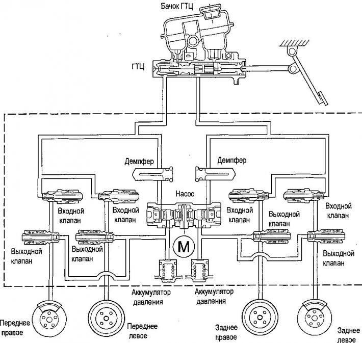
1. Hydraulic modulator; 2 Bracket; 3. Front wheel speed sensor; 4. Rear wheel speed sensor.
ABS Elements Placement
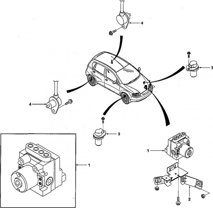
1. Hydraulic modulator block; 2. Bracket for mounting the hydraulic modulator unit; 3. Front wheel speed sensor; 4. Rear wheel speed sensor.