


This type of ignition system without a distributor breaker operates on the "excess spark" method. The cylinders are paired with opposite (1-4 or 2-3). The spark occurs simultaneously in the cylinder in which the piston is in the compression phase and in the cylinder in the exhaust phase. The cylinder in the exhaust phase requires a very small amount of energy to spark the spark plug. The remaining energy is used by the spark plug in the cylinder in the compression phase. The ignition coil cannot be repaired, so it is necessary to replace the entire unit.
These systems use the EST signal from the ECM to control the electronic ignition system. The ECM uses the following data.
- Engine load (manifold pressure or vacuum).
- Atmospheric (barometric) pressure.
- Engine temperature.
- Supply air temperature.
- Crankshaft position.
- Engine speed (rpm).
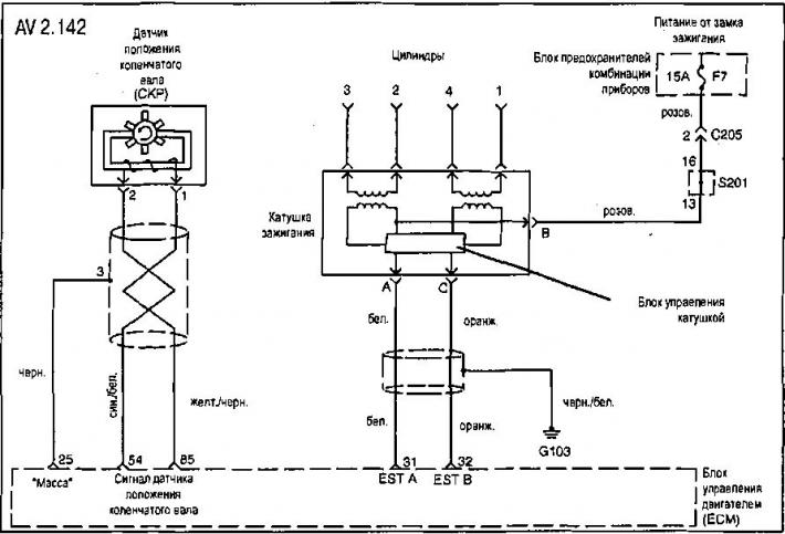
Checking the ignition system
Check all spark plugs for wet, cracked, burnt, heavily fouled or improperly gapped plugs. Replace spark plugs if necessary. Check for spark from all spark plug wires when the starter is engaged. It is important to check for spark in all cylinders to identify problems with the ignition coil input and output signals.
Check for spark from all high voltage ignition wires when the starter is engaged.
Measure the resistance of the high-tension spark plug wires (30 kOhm). Replace any high-tension spark plug wires whose resistance is greater than the specified value.
Check the signals from the ECM to the ignition coil. It is recommended to use an oscilloscope when checking the ECM spark signals, as many intermittent faults may go unnoticed when using a voltmeter. If the ECM spark signals are OK, the ignition coil may be the cause of the fault.
Check the functionality of the crankshaft position sensor, for which:
- measure the resistance between terminals 1 and 2 of the crankshaft position sensor connector (400-600 Ohm) with the connector disconnected;
- measure the voltage between terminals 1-3, 2 - crankshaft position sensor connector and 1 (crankshaft position sensor connector)
- G103 ("mass"). In all cases, the voltage should be within 1.3-1.5 V.
Disconnect the ignition coil connector. When the starter is turned on, measure the voltage at terminals A and C of the ignition coil connector (0.2-2.0 V). Check the integrity of the wires between terminals C (ignition coil connector) and A19 (eCM connector), and also between terminals A (ignition coil connector) and A1B (eCM connector).
Check the power supply to terminal B of the ignition coil (pink wire) via connectors S201 C205 from fuse F7 (15 A) (fuse box) using a test light (probe).
[For details, visit the website chevyman.ru]