


Complete disassembly of the generator in a garage is not recommended, so if necessary, it is better to contact a workshop specializing in generator repair. This subsection shows only the replacement of the voltage regulator assembly with the brush unit and bearings.
1. Remove the generator from the vehicle (see "Removal and installation the generator").
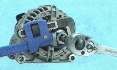
2. Holding the generator shaft with a hex key, unscrew the pulley mounting nut...
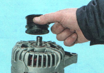
3. ...and remove the pulley from the shaft.
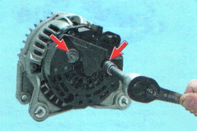
4. Unscrew the two nuts of the generator power terminals.
NOTE: The power terminal nuts also secure the protective cover.
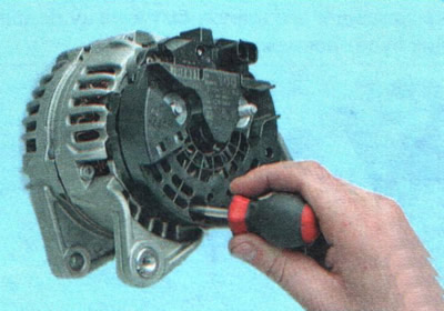
5. Remove the screw securing the protective cover...
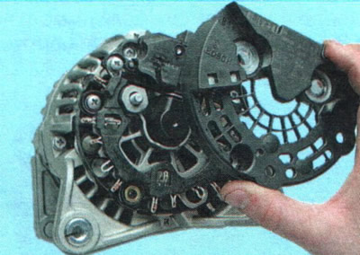
6. ...and remove the casing.
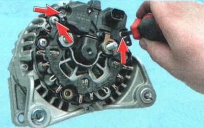
7. Remove the three screws securing the voltage regulator with the brush assembly...
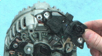
8. ...and remove the voltage regulator.
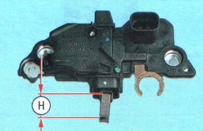
NOTE: This is what the voltage regulator looks like with the brush assembly removed from the generator. Check the protrusion of the brushes in a free state. If the dimension H is less than 3 mm, replace the brushes or the brush assembly as a whole. Check the ease of movement of the brushes in the brush holder. If they stick, the brush assembly must also be replaced.
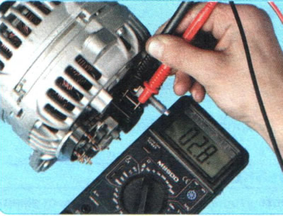
9. Check the rotor winding resistance with an ohmmeter (tester) by connecting it to the contact rings. If the ohmmeter shows infinity, then there is a break in the windings and the rotor needs to be replaced.
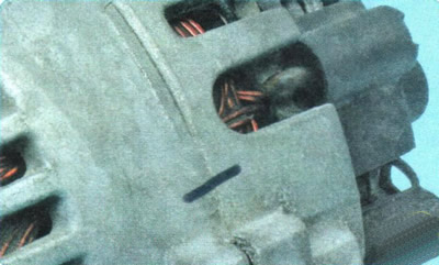
10. Mark (for example, with a marker) the relative position of the generator covers to ensure alignment of the holes in the generator mounting feet during reassembly.
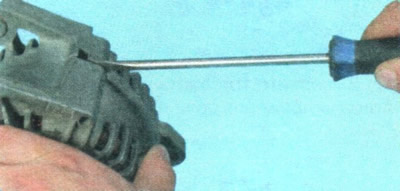
11. Unscrew the four tie bolts. Use a screwdriver to pry between the covers...
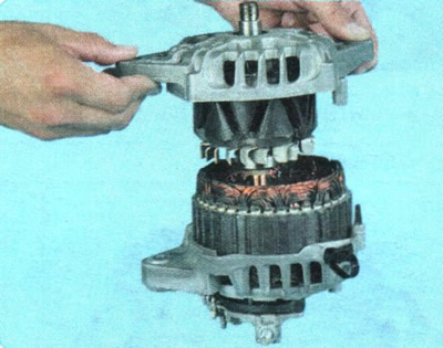
12. ...and remove the front cover together with the rotor.
NOTE: The rectifier unit, stator winding and rear cover are a single unit and cannot be further disassembled in a garage, since the stator winding terminals are connected to the rectifier unit terminals by contact welding.
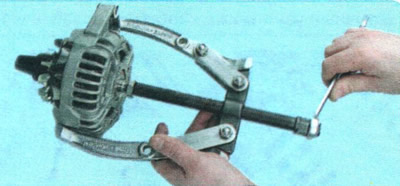
13. Press the rotor out of the front cover.
USEFUL TIP: To avoid damaging the rotor shaft threaded end with the puller screw, screw the pulley mounting nut onto it flush with the end of the shaft.
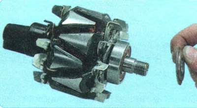
14. Remove the spacer washer from the front end of the rotor shaft...
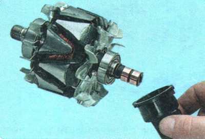
15. ...and from the rear bearing of the rotor shaft, a centering sleeve.
16. Inspect the plastic centering sleeve of the rear bearing of the rotor shaft. The centering sleeve should be tightly installed in the hole of the cover. If the bearing is correctly seated in the sleeve, there should be no traces of the outer ring of the bearing slipping on it.
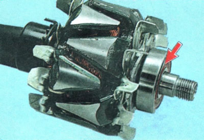
17. Inspect the front bearing of the rotor shaft. If, when rotating the bearing, you feel play between the rings, rolling or jamming of the rolling elements, damaged protective rings or grease leaks, replace the bearing. To replace the bearing, press it off the rotor shaft with a universal puller. Press the new bearing onto the shaft, applying force only to its inner ring.
CAUTION: Pressing the bearing on with force applied to the outer race will damage the bearing.
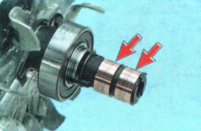
18. Inspect the contact rings. If they have burrs, scratches, marks, wear marks from brushes and other damage, the rings must be ground. If the damage to the rings cannot be removed with sandpaper, you can turn the rings on a lathe, removing a minimum layer of metal, and then grind them.
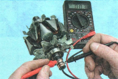
19. Check the rotor winding resistance with a tester by connecting it to the contact rings. The resistance should be approximately 3-5 Ohms. If the tester shows infinity, then there is a break in the rotor winding - the rotor must be replaced.
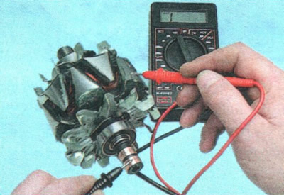
20. Check for a short circuit between the rotor winding and the housing by connecting the tester leads to any slip ring and the rotor housing. The tester should show infinity.
21. Check the ease of rotation of the bearing from the contact rings. If, when rotating the bearing, there is play between the rings, rolling or jamming of the rolling elements, damage to the protective rings or grease leaks, the bearing should be replaced. To do this...
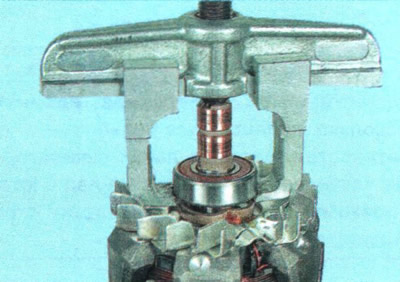
22. ...press the bearing off the rotor shaft.
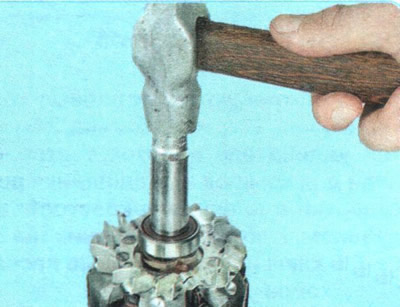
23. Press the new bearing onto the rotor shaft until it stops against the shaft flange, applying force only to the inner ring of the bearing through a mandrel of suitable diameter.
24. Assemble the generator in the reverse order of disassembly, orienting the generator covers and stator according to the previously made marks.